04 — Biomedical Engineering
Biology, electronics, computation
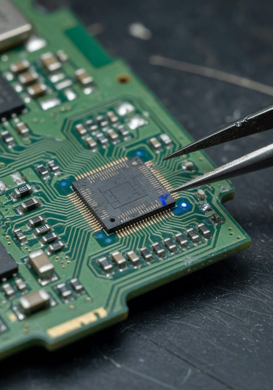
A complete vitals instrument, about the size of a fingernail.
Biomedical sensor design and signal processing for medical use, built into a module near 1.5 by 1.5 cm — its own microcomputer, a MEMS sensor array, and wireless everything, reading heart rate, temperature and SpO2.
Biomedical engineering, for me, sits at the intersection of biology, electronics and computation — three fields that have to agree before a measurement means anything.
The work is biomedical sensor design and signal processing for medical applications: turning a body signal into a number a clinician would trust, and doing it on hardware small enough to live on the body rather than beside it. Biology decides what is worth measuring, electronics decides how to capture it, and computation decides what the capture actually means.
The thread that runs through all of it is smart devices for monitoring and intervention — devices that do not just sense but can act on what they read. The clearest expression of that is a biomedical microchip: a complete vitals module near 1.5 by 1.5 cm that reads heart rate, temperature and SpO2, processes them on its own microcomputer, and reports over a wireless link.
I build on Nordic, Texas Instruments and Maxim Integrated platforms, and the same instinct carries into micro-robotics applied to biomedical systems — the move from a device that reports to one that can position and act at small scale.
edge length of the complete vitals module — a full instrument inside roughly 1.5 by 1.5 cm
vital signs read at once: heart rate, temperature, and SpO2 blood-oxygen saturation
order of the MEMS sensor die — micro-electromechanical sensing on the same board as the processor
external connectors — the module charges by induction and talks over Bluetooth Low Energy
Everything an instrument needs, on 1.5 cm of board.
A complete vitals module
A microcomputer, a sensor array, a radio, a battery and its own charger — all in roughly 1.5 by 1.5 cm.
The biomedical microchip I work toward is not a single sensor — it is a complete module on the order of 1.5 by 1.5 cm with its own microcomputer, a MEMS sensor array, a signal concentrator, an algorithm processor, a Bluetooth antenna, a micro LiPo battery and wireless charging.
Each of those blocks would normally be its own board. The work is fitting them onto one footprint without the analog stages, the radio and the processor interfering with each other — a packaging and integration problem as much as an electronics one.
- On-module microcomputer
- MEMS sensor array
- Signal concentrator + algorithm processor
- Bluetooth antenna, micro LiPo battery, wireless charging
Vitals module — block inventory
- Form factor
- Complete module, ~1.5 × 1.5 cm
- Microcomputer
- On-module MCU — its own compute, not a host
- Sensor array
- MEMS array, ~1 mm² class dies
- Signal concentrator
- Front-end that gathers and conditions the sensor streams
- Algorithm processor
- On-module processing of HR · temperature · SpO2
- Radio
- Bluetooth antenna — Bluetooth Low Energy link
- Power
- Micro LiPo battery
- Charging
- Wireless, inductive coil — no connector
- Platforms
- Nordic · Texas Instruments · Maxim Integrated
The blocks that make it an instrument, not a sensor.
Five functional blocks share one board. Each tab is one of them — what it does and why it earns the space it takes on a footprint this small.
Its own compute, on the module
The module carries its own microcomputer rather than depending on a phone or a base station to think for it. That means the sampling, the timing and the first pass of signal processing all happen on the board itself, where the sensors are.
Keeping compute local keeps the radio quiet. The module can read, process and decide what is worth transmitting, instead of streaming raw samples and burning the battery on the antenna.
- On-module MCU — not a tethered peripheral
- Sampling and timing handled locally
- First-pass processing before anything is sent
Micro-electromechanical sensing
The sensing is a MEMS array — micro-electromechanical structures fabricated at roughly the square-millimetre scale, on the same board as the processor. MEMS is what lets a temperature element, an optical front end and a motion reference share a footprint this small.
Putting the array next to the processor shortens every analog path. The signal is digitized close to where it is born, before noise has room to accumulate.
- MEMS dies on the order of 1 mm²
- Co-located with the processor on one board
- Short analog paths, early digitization
Gathering the streams in one place
Three vital signs arrive on different physical principles — optical, thermal, electrical. The signal concentrator is the front end that gathers those separate streams, conditions them, and hands them to the algorithm processor as a coherent set.
It is the part that turns three sensors into one measurement event, time-aligned, so the heart-rate, temperature and SpO2 readings describe the same instant rather than three drifting clocks.
- Conditions optical, thermal and electrical inputs
- Time-aligns the three streams
- Feeds one coherent set to the processor
Turning signals into vitals
The algorithm processor is where conditioned signals become numbers a clinician would recognize. Heart rate comes out of the optical pulse, SpO2 out of the ratio between two optical wavelengths, and temperature out of the thermal element.
Doing this on the module means the device reports vitals, not waveforms. The processing that would normally live in an app or a cloud service runs at the source.
- Heart rate from the optical pulse
- SpO2 from a dual-wavelength ratio
- Temperature from the thermal element
Bluetooth out, induction in
The module talks over Bluetooth Low Energy through an on-board antenna, and runs on a micro LiPo battery. There is no data cable and no power cable.
Charging is wireless — an inductive coil takes energy across the gap so the enclosure can stay sealed. Nothing about the device requires opening it or plugging into it.
- Bluetooth Low Energy link, on-board antenna
- Micro LiPo battery
- Inductive wireless charging — sealed enclosure
From a body signal to a number, in one pass.
Three vital signs travel the same path on the module: sensed by the MEMS array, gathered by the signal concentrator, processed by the on-module microcomputer and algorithm processor, and sent out over Bluetooth Low Energy to a paired app. The diagram traces that path; the process flow names each stage.
What leaves the module is the result, not the raw waveform. Reading and processing happen at the source, so the radio carries vitals — heart rate, temperature, SpO2 — rather than a stream of samples.
Vitals signal chain
Three signals in, three numbers out.
Heart rate, temperature and SpO2 each begin on a different physical principle — optical, thermal, optical-ratiometric — and the chain brings them onto one timeline. The MEMS array senses, the concentrator conditions and aligns, and the processor resolves each stream into a value.
Keeping all of this on the module is the point. The device that touches the body is also the device that does the thinking.
- HR from the optical pulse
- Temperature from the thermal element
- SpO2 from a dual-wavelength ratio
Vitals chain — sensor to app
- 01 MEMS array Optical, thermal and electrical front ends sense the body at roughly the square-millimetre scale.
- 02 Signal concentrator The three streams are gathered, conditioned and time-aligned into one event.
- 03 MCU The on-module microcomputer samples, times and runs the first pass of processing.
- 04 Algorithm processor Conditioned signals become vitals: heart rate, temperature, SpO2.
- 05 BLE Only the results, not the raw waveforms, leave over Bluetooth Low Energy.
- 06 App A paired app receives the vitals; the module keeps running on its own compute.
Sensor, MCU, BLE, app — the data path drawn out.
The data path
The module senses, decides, and sends only what matters.
The path from sensor to app is short and deliberate. The MEMS array feeds the MCU; the MCU processes on the module; the result goes out over Bluetooth Low Energy to a paired app. The raw samples never leave.
That ordering is what makes the device practical to wear. A module that streamed every sample would drain its micro LiPo battery on the radio; one that decides locally can run on it.
- Sensor → MCU → BLE → app, in that order
- Processing happens before transmission
- Only results cross the radio, not raw samples
A module that decides what is worth sending can live on a micro battery; one that streams everything cannot. The radio is the most expensive thing on the board.
Heart rate, temperature, SpO2 — each earned differently.
The three vitals are not read the same way. Heart rate and SpO2 are optical and share a front end; temperature is thermal and stands apart. Reading all three on one small module means each signal has to be recovered cleanly without the others getting in the way.
Each tab below is one signal: where it comes from, and the part of the signal processing that actually decides whether the number is trustworthy.
Counting beats from light
Heart rate is read optically. Light is sent into tissue and the portion that returns is modulated by the pulse of blood with each beat; recovering that periodic signal and counting its peaks gives the rate.
The hard part is not the optics, it is the rejection — motion and ambient light look a lot like a pulse. The signal chain is built to separate the real periodicity from everything that imitates it.
- Optical pulse modulation as the source
- Peak detection on a periodic signal
- Motion and ambient light rejected, not averaged away
A thermal element, read steadily
Temperature comes from a thermal element on the MEMS array. The measurement itself is simple; the discipline is in referencing it so the reading reflects the body and not the self-heating of the electronics next to it.
On a module this small the processor sits millimetres from the sensor, so thermal layout is part of the measurement, not an afterthought.
- Thermal element on the MEMS array
- Referenced against on-board self-heating
- Thermal layout treated as part of the spec
Oxygen from a ratio of wavelengths
SpO2 — blood-oxygen saturation — is recovered from the different ways oxygenated and deoxygenated hemoglobin absorb two optical wavelengths. The ratio of the two pulsatile signals maps to a saturation percentage.
It shares the optical front end with heart rate, which is part of why a single small module can report both: the same light path carries two measurements once the wavelengths are separated.
- Dual-wavelength optical absorption
- Ratio of pulsatile signals → saturation %
- Shares the optical front end with heart rate
Charging across a gap, so nothing has to open.
Inductive wireless charging
A coil on each side, energy across the gap.
The module charges by induction. A coil in the charger drives an alternating field; a coil on the module picks it up and rectifies it back into charge for the micro LiPo battery. No contacts, no connector, nothing to corrode.
On a body-worn device that matters for more than convenience: a sealed enclosure with no charging port is easier to clean and keep intact. The same logic that put the radio on the board put the charger off it.
- Driver coil in the charger, pickup coil on the module
- Rectified to charge the micro LiPo battery
- No contacts — the enclosure stays sealed
Where the 1.5 cm goes — the module, exploded.
Fitting a microcomputer, a MEMS array, a signal concentrator, an algorithm processor, a Bluetooth antenna, a micro LiPo battery and a charging coil into 1.5 by 1.5 cm is a stacking problem. The blocks layer rather than sit side by side, and the order of the layers is chosen so the analog stages stay away from the radio.
The exploded view below pulls those layers apart. In the built module they collapse into one footprint; the parts that have to be quiet sit furthest from the antenna, and the coil and battery take the back where they shield nothing critical.
~1.5 × 1.5 cm, exploded
Layers chosen so the antenna does not poison the analog.
Read top to bottom, the stack is: the MEMS sensor array facing the body, the signal concentrator and algorithm processor with the MCU, the Bluetooth antenna, and the micro LiPo battery with the charging coil at the back.
Putting the radio between the processor and the power layer keeps the sensitive front end and the antenna apart. On a footprint this small, that placement is the difference between a clean reading and a noisy one.
- MEMS array faces the body
- Concentrator, algorithm processor and MCU together
- Bluetooth antenna layer
- Micro LiPo battery + charging coil at the back
Platforms — the parts behind the module
- Nordic
- Bluetooth Low Energy SoC and radio stack
- Texas Instruments
- Mixed-signal front ends and low-power MCUs
- Maxim Integrated
- Biopotential and optical analog front ends
- Integration target
- One module, ~1.5 × 1.5 cm
- Link
- Bluetooth Low Energy
- Power input
- Inductive wireless charging
From a device that reads to a system that acts.
A monitor is the first step. The objective is smart devices for monitoring and intervention — and, beyond that, micro-robotics applied to biomedical systems.
A vitals module that reads heart rate, temperature and SpO2 is a monitoring device. The more interesting line of work is intervention: devices that can act on what they read, at the same small scale where the sensing happens.
Micro-robotics applied to biomedical systems is where biology, electronics and computation meet again — a system that does not only report a measurement but can position and act on it. The module is the sensing half of that picture; the actuation half is the work the sensing makes possible.
Biomedical sensor design
Designing the front ends that turn a body signal — optical, thermal, electrical — into something an algorithm can read, at the scale where the sensor fits on the same board as the processor.
Signal processing for medical use
Recovering heart rate, temperature and SpO2 from noisy inputs, with rejection of motion and ambient interference rather than blind averaging.
Smart monitoring devices
Devices that monitor continuously and can act on what they read — the step from a sensor that reports to a device that intervenes.
Biomedical microchips
Complete vitals modules near 1.5 by 1.5 cm with their own microcomputer, MEMS array, signal concentrator, algorithm processor, radio, battery and wireless charging.
Micro-robotics for biomedical systems
Micro-robotics applied to biomedical systems — moving from a module that senses to a system that can position and act at small scale.
Platform integration
Building on Nordic, Texas Instruments and Maxim Integrated parts, so the radio, the mixed-signal front ends and the analog stages each come from a platform suited to them.
The principles underneath the module.
The signals change and the platforms change, but the rules behind the work do not.
These are the principles I apply whether the target is a heart-rate front end, a full vitals module, or a step toward micro-robotics applied to biomedical systems — the part that keeps the engineering repeatable rather than incidental.
Sense at the source
Put the MEMS array on the same board as the processor so the signal is digitized close to where it is born, before noise accumulates.
Process on the module
Report vitals, not waveforms. Local compute keeps the radio quiet and the battery alive.
Reject, do not average
Motion and ambient light imitate a pulse; the chain is built to separate the real signal from what mimics it.
Seal the enclosure
Wireless charging and a wireless link mean no connectors — nothing about the device requires opening it or plugging in.
Match the part to the stage
Nordic for the radio, TI for mixed-signal and MCUs, Maxim for the analog front ends — the right platform for each job.
From sensing toward intervention
A monitor is the start. Micro-robotics applied to biomedical systems is the path from a device that reads to one that acts.
Sense at the source, process on the module, and send only what matters — everything else is packaging around those three decisions.
Open to the right work
If your problem starts on the body and ends in a number you can trust, that is the work I want.
If you are holding a problem that doesn't fit inside one field, that is the conversation I want.